Robowaiter Interfacing Circuitry
The H-Bridge
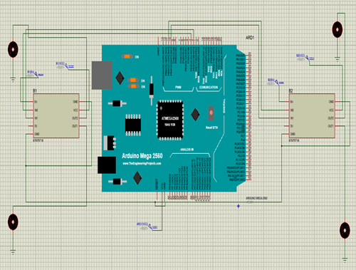
The H-Bridge comes first in Robowaiter Interfacing Circuitry. The H-Bridge is mainly used for applying PWM to the motors. The following diagram shows the interfacing of the H-Bridge with Arduino. The H-Bridge pins can only be used for PWM control if we connect its input pins to PWM pins of Arduino. The output pins of H-Bridges are connected to the motors.

IR Sensors
For interfacing IR sensors the analog pins of Arduino are used. Analog Pins i.e. A0-A15 gives the value of IR Sensor which it reads from black and white surface. Ground pin of the IR sensor is connected to the ground of Arduino.

Keypad
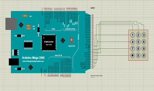
The keypad is used for assigning table numbers. The rows and columns of the keypad are connected to the digital pins of Arduino. Its state is checked whether it is low or high for the placement of order to the destination i.e. Table number.

LCD
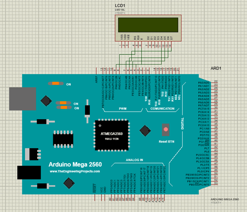
The LCD displays the table number assigned by the manager. It is connected to the PWM or digital pins of Arduino. The interfacing of the LCD is shown in the figure.


